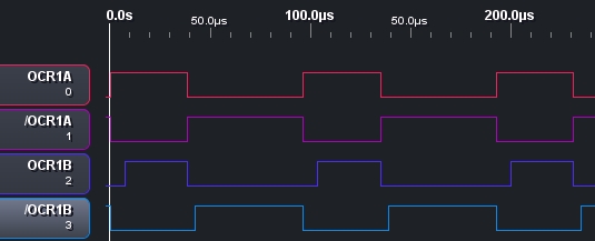
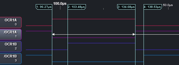
The ATtiny 25/45/85 datasheet has an intriguing section about the “dead time generator” that I found a little confusing. A little practical example helped me to understand it. The code and logic analyser trace (made using the same analyser and client mentioned in previous posts) appear below. This is just an example to understand how it works. Real applications seem to be principally brushless DC motor control (pdf).
The setup below uses both A and B compare registers with the same compare value and applies some dead time to the B output so that the effect can be easily seen. I was also tempted to play around with the C compare register which sets the value at which the counter resets. Read the code comments for more…
1 2 3 4 5 6 7 8 9 10 11 12 13 14 15 16 17 18 19 20 21 22 23 24 25 26 27 28 29 30 31 32 33 34 35 36 37 38 39 40 41 | //set the top count give whole number percentage duty cycles const unsigned char top = 99; //40% duty cycle if top=99 const unsigned char compare = 39; //prescale CLK/8, 8Mz clock and div8 prescale -> 1MHz tick -> appropx 10kHz output with top=99 const unsigned char prescaleTimer = (1<<CS12); //prescale CLK/4. const unsigned char prescaleDead = (1<<DTPS11);// div 8 = (1<<DTPS11) | (1<<DTPS10) // with CLK/4 prescale and 8MHz clock the dead time is 0.5uS per LSB. // Dead time is delay to rising edge of signal const unsigned char deadHigh = 0x0F; //8uS dead time for OCR1B. Max 0x0F const unsigned char deadLow = 0x08; //4uS dead time for /OCR1B int main(void) { //set data direction for output compare A and B, incl complements DDRB = (1<<PB4) | (1<<PB3) | (1<<PB1) | (1<<PB0); //setup timer1 with PWM. Will be using both A and B compare outputs. // both compares will be the same but only B will have dead time applied OCR1A = compare; OCR1B = compare; TCCR1 = (1<<PWM1A) | (1<<COM1A0); //Compare A PWM mode with complement outputs GTCCR = (1<<PWM1B) | (1<<COM1B0); //Compare B PWM mode with complement outputs //PLLCSR is not set so the PLL will not be used (are using system clock directly - "synchonous mode") //OCR1C determines the "top" counter value if CTC1 in TCCR1 is set. Otherwise "top" is normal: 0xFF OCR1C = top; TCCR1 |= (1<<CTC1); TCCR1 |= prescaleTimer; //setup dead time for compare B. Note the prescaler is independent of timer1 prescaler (both receive the same clk feed) DTPS1 = prescaleDead; //DT1A is unset - output A has no dead time DT1B = (deadHigh<<4) | deadLow; while(1) { //do nothing } } |


End Stuff
Source code is also available from github.
All code is copyrighted and licenced as follows:
***Made available using the The MIT License (MIT)***
Copyright (c) 2012, Adam CooperPermission is hereby granted, free of charge, to any person obtaining a copy of this software and associated documentation files (the “Software”), to deal in the Software without restriction, including without limitation the rights to use, copy, modify, merge, publish, distribute, sublicense, and/or sell copies of the Software, and to permit persons to whom the Software is furnished to do so, subject to the following conditions:
The above copyright notice and this permission notice shall be included in all copies or substantial portions of the Software.
THE SOFTWARE IS PROVIDED “AS IS”, WITHOUT WARRANTY OF ANY KIND, EXPRESS OR IMPLIED, INCLUDING BUT NOT LIMITED TO THE WARRANTIES OF MERCHANTABILITY, FITNESS FOR A PARTICULAR PURPOSE AND NONINFRINGEMENT. IN NO EVENT SHALL THE AUTHORS OR COPYRIGHT HOLDERS BE LIABLE FOR ANY CLAIM, DAMAGES OR OTHER LIABILITY, WHETHER IN AN ACTION OF CONTRACT, TORT OR OTHERWISE, ARISING FROM, OUT OF OR IN CONNECTION WITH THE SOFTWARE OR THE USE OR OTHER DEALINGS IN THE SOFTWARE.