Change Wheel Calculator for Warco 918 Lathe

Here is a spreadsheet to calculate all the thread pitches possible on a Warco 918 lathe using the change wheel set provided with the machine :  XLSX (newer versions of Excel) and XLS (Excel 97 and 2003, also works in LibreOffice/OpenOffice).

The cells are all locked except D4, which should be set to “y” or “n” depending on whether the 120/127 tooth gearing will be in use (see the plate attached to the lathe). Note that there are three worksheets for mm/rev, inch/rev and tpi.

Use should be self-evident, but in case not, here is an example.

Looking at the “mm per rev” sheet:

  • Put “y” in cell D4 because that gives results in nice round numbers
  • Assume you want 1.5 mm/rev
  • See this appears in four cells: I13, I14, F19 and C24
  • Choose F16 (on a whim, or maybe you already had a 36 tooth wheel in position b)
  • Change-wheels (where a and b are as on the plate attached to the lathe) to use are: a=45 tooth and b=36 tooth
  • The gearbox should be set to no. 4
  • Note that the Warco lathe-plate gives the C24 configuration.

If unsure, check you understand it by choosing a few of the pitches given on the lathe-plate and confirming that the change-wheels and gearbox settings you determine from the spreadsheet match the “right answer”.

Warning: I might have made a mistake so always try out on a piece of scrap and measure the result.
 

Liking LibreCAD – Free cross-platform 2D CAD

I’d been using DraftIT for a number of years when I wanted to be able to work on plans using both my home computer (Win XP) and work laptop (Ubuntu Linux) while the family uses the home PC. After some searching, I came across what is now called LibreCAD. It takes a little while to adjust (I suppose this is always the case) but I must say “it works for me”. It isn’t too hard to pick it up by trying and it is possible to do simple stuff without having to understand everything it does.

Best of all, it saves as DXF format, while this only comes with the “Pro” version of DraftIt which costs £99.  DXF is a de-facto standard so this makes the drawings more sharable and – maybe more important – gives me more confidence in being able to read/alter drawings for longer (e.g. if the makers of DraftIT vanish).

Recommended!

Good Results with Cheap TCMT Tools

From the outset of setting up my metalwork shop I decided to use tungsten carbide tipped tools for the lathe. I just don’t want to be bothered with the fiddle of sharpening and having to keep changing the shims under the tools. This is at variance with the received wisdom that the low power and low spindle speeds of small lathes like my Warco 918 indicate that HSS tooling is appropriate.

The first set was from Warco and I never really got good results with the CCMT left and right hand tools, especially on aluminium but the DCMT tool with the point symmetrically arranged seemed much better. This encouraged me to try a cheap TCMT set from Chronos and must say they seem like the business. I think the small radius points and lower point angle is what allows me to get really quite good finishes on even small parts with small depths of cut in Aluminium with a max of 1800 RPM. Brass and steel are also fine.

So, my recommendation: if you are starting out get a set of 5 TCMT tools.

BTW, tip codes are generally of the form TCMT 110204, where “04” designates a 0.4mm radius on the cutting tip.

DIY Milling Machine Rev Counter for Under £5

As I have a variable speed millling machine without a digital readout (its an Axminster SIEG X2) and wanted a bit more control at the hundreds-of-RPM level than I could get by listening to the pitch of the machine or watching the chuck, some technology was required…

Cycle Computer Rev Counter on an X2 Milling Machine

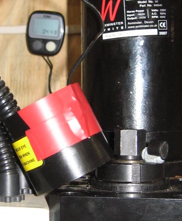
The answer was simple and cheap: use a cheap cycle computer that can read RPM (I got a new one for under a fiver off ebay). I carefully dismantled the sensor to expose the reed switch inside, which I taped to the outside of the cover for the top end of the spindle on the X2. I attached the magnet that normally fixes to the cycle wheel to the top of the spindle with a blob of blue-tack so that it ran close to the cover. Thats it! I suppose a better attachment could be achieved than blue-tack but it works fine at the relatively low spindle speeds I am interested in and I just remove the magnet afterwards.

How to Make and Use a Split Bush (Chucking Piece) for Concentric Turning

I’ve recently been making a Stuart 10V with the help of the Andrew Smith/Pengwern building guide. At one point they recommend the use of a split bush to afford a greater degree of concentricity in turning the piston rod (and both the piston and cross-head attached to this). A sketch of the split bush is provided with the throw away comment that its use requires no description. OK, that much I agree with but the making of the device led me astray.

The basic idea of the split bush is to get around the fact that the lathe chuck is likely to be a wee bit off truely concentric to its rotation axis. i.e. even perfectly cylindical rod in an unworn chuck will not rotate about its centre. The split bush is bored in situ, which does guarantee the hole is centred on the axis of rotation and the work is held in the hole. In the 10V, there is a 5/32″ piston rod and 1/8″ valve rod that need to be treated in this way. By the way, I use a Warco 918, a relatively cheap Chinese lathe and I have demonstrated that the chuck is about 0.001″ out.


(click to enlarge)

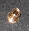
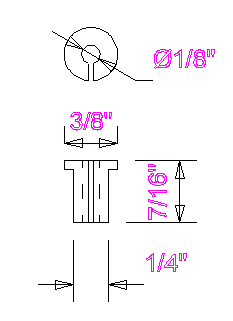
A split bush for 1/8″ diameter rod. The shoulder should sit againt the outer nose of the chuck, which is tightened to cause the bush to grip the work piece

The problem with being a self-taught novice is that you don’t know some simple stuff and don’t know which of various factors actually matter. Paranoia about defeating the whole point of the operation by removing the bush from the lathe between boring the hole and using it – would the hole now be true – led me to make the bush the wrong way. Part of the reason for this is that I had previously made a larger (1 1/4″) chucking ring where a boring bar had been used. The error I made was to drill and ream (actually I use home made D-bits) the hole after cutting the slot in the side. This doesn’t matter when using a boring bar but it does when drilling, especially as the slot size gets close to the hole size. I didn’t notice this problem with the 5/32″ piece bit it became obvious with the 1/8″ piece (see below):

I didn’t spot this until using the bush as (remember the paranoia) the bush wasn’t removed after boring and before using it. Its not like I didn’t know about drill wander but I was surprised it made so much difference and I was still paranoid. It seemed like there was no way ahead. Some Googling was done and eventually I found more than an assumption that everyone knew how to make/use these devices; I found enough to get me to have another go, the proper way. Actually I had tried to find out how to make split bushes before but not found anything so had a go… the wrong way. I decided to write this post in case anyone else needs a bit of help to do it the right way the first time.

How to Make a Split Bush Properly…

(this one did indeed seem to be right – I checked quite carefully)

  1. Face the end of some brass and turn down the 1/4″ section.
  2. Part off or remove and saw off
  3. Re-chuck, ensuring the shoulder seats on the chuck nose “nicely”
  4. Face off, centre drill, drill 3mm and ream/D-bit 1/8″ (I love mixing units)
  5. Identify one of the chuck jaws (I centre punched the chuck backplate) and mark the nascent bush to it may be precisely aligned with this jaw. A light centre-punch is nice and permanent.
  6. Remove the piece, insert a piece of rod into the centre and cut the slot in the opposite side to the marked point. The rod avoids hard-to-remove swarf buildup in the inside which will interfere with the workpiece. I’ve started using a Dremel tool for little jobs like this.
  7. Return to the lathe chuck, reseat carefully and lightly tighten the chuck, insert the work piece, tighten the chuck fully and there you are…