Some incomplete notes from a recent conversion of 3 old cap lamps to run off white LEDs extracted from a cheap (yet astonishingly bright) headtorch and powered by Lithium-based cells salvaged from an old laptop battery. One of the 3 caplamps was from a 1991 Apex 2 and the others were ex-NCB pit-lamps of unknown age.
Raw Materials
- some pieces of brass (see below)
- a 5W, 270 lumen headtorch powered by 3xAAA cells. Cost less than £5 incl postage from Hong Kong via ebay. I bought a few cheap torches looking for suitable de-mountable modules (see the photos below). A simple on-off type was chosen rather than multi-mode (bright, dim, flashing…)
- A pair of 18650 3.7V Lithium cells with solder tags or salvaged from a laptop battery
- A cheap “travel charger” for these cells. I bought a pair of cells with a charger for about £5 via ebay and use the cells in a hand-held zoomable torch that serves as a caving backup and dark-corner-probe.
- A potting box and potting resin (Maplin does suitable)
- Heat-sink compound (see Maplin’s again)
- a few solder tags, a couple of M3 machine screws
- 4x #40-40 stainless steel cap-screws at least 3/4″ long (this is an American standard thread. Try radio control model suppliers)
- An old caving lamp
- A through-headset charging part. I had one of these “lying about” but they may be hard to find these days. If so, adapt the design with charging connectors on the battery some-how.
Headset- Components to Make and Fitting
Remove all the components from the headset except the negative wire (fixed to the body) and the switch moving part and its spring-contact. I actually removed all parts to overhaul everything.
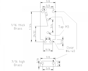
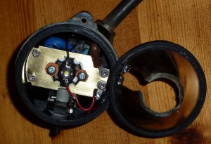
See the dimensioned drawings and photo of the finished result below (both are available in larger size by “clicking” the image). The dimensions on the plate are approximate; be prepared to make some adjustments and in particular note that the photo shows a small cutout to clear the on/off switch. I tapped the holes to secure the LED modules but you could just drill to clear an M3 screw and use a nut on the rear.


The smaller part on the drawings is a pillar that will be located at the top of the lamp where the pilot lap is. This needs rounded corners to fit. For the Apex 2 caplamp, this fits neatly without any work on the caplamp body. For my other two, there is a lump to machine away. I used a slot-drill in a pillar-drill but a router-cutter would probably work. Beware that this process exposes some brass. This brass is actually part of the (negative) circuit embedded in the body and it must not be allowed to contact the pillar. The pillar should, however, have a good contact with the body in order to conduct heat away from the LED. I simply milled a recess over it to avoid contact.
Heat-sink compound was applied between the LED module and the plate and both top and bottom of the “pillar”.
The #4-40 screws will have to be made the correct length: 2 at 3/4″ and 2 at slightly less than 5/8″ (both dimensions include the head of the cap-screw – sorry I failed to measure thread-length.) . These screws fasten the brass plate to the cap lamp body. “Clear” in the diagram means that the screw will easily pass through; these are plain drilled holes.
The wiring is mostly obvious from the photograph. The negative wire from the LED is attached to one of the switch contacts using a solder-tag. The other switch contact is not used and was not refitted. Don’t trust the pictures – work it out!
Small padding washers are used for the LED module hold-down. These could be old inner tube, although I used some gasket paper. The idea is just to reduce the risk of damage.
The reflector will need to be sawn off as in the photograph. A Dremel tool (etc) is quite handy for this. Find a way of marking off the cut height or mount the Dremel at a fixed height over a flat surface to get this cut neat, even and to avoid cutting off too much. The LED module I used had quite good combination of central beam and spill-out and the end result with the reflector as shown is quite satisfactory.
Battery Pack
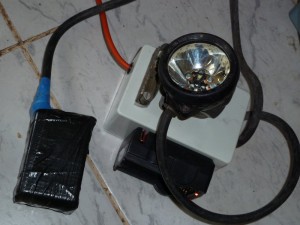
This is just a pair of 18650 cells in parallel cast in potting compound. A piece of rubber was placed beneath the cells to avoid direct contact with the box anywhere. Make sure the hole for the cable is tight otherwise compound will leak out. I would have used a grommit but bought the wrong size. An outer protective layer of inner tube and gaffer tape finishes the job off. This will he helmet mounted and only be used for light caving so is not “bomb proof”; I do not expect to bash my head against many long awkward passages.
Charger
This basically involves mounting the “travel charger” on the side of a box, having soldered mains supply to its circuit board and soldered some take-off wires for the head-set contacts. It is probably best to avoid charging via headset at the same time as separate cells.

NB: the Apex 2 headset was bodged to allow for through-headset charging.
I thought you might be interested, I bought one of the first Apex 2 caving lamps that come on the market, the reason I went for the Apex and not the FX 2 was the Apex used the Oldem cap lamps and I felt they were more robust then the FX 2, after all these years I am still getting in excess of 8 hours light from it.
I thought I would share that with you.
Regards.
John Riley.