The DFU bootloaders that Atmel supplies, as Intel HEX files, for its Xmegas have pre-determined pins used to sense whether or not to skip the bootloader and start the application, or to register the device to the host PC via USB. These are slightly hidden on the Atmel website and the source code requires IAR to compile it (and an easy port to AVR-GCC is thought to be impossible on size grounds). A number of threads on AVRFreaks have discussed this matter, including: “Building bootloader for ATXMega16A4U from avr1916.zip” and “Where’s the DFU bootloader?“. I didn’t fancy installing IAR, but was intrigued by comments about dis-assembling the HEX files and tweaking bytes. The process was not explained, but in spite of starting off totally “in the dark”, an evening of fumbling and fiddling got me through to a result that worked. This post explains the process, in case anyone else wants to do the same. It is also my notes-to-self for when I forget!
Background
The Atmel application note AVR1916 has essential background info and the associated zip file contains the Intel HEX files for different xmega chips. The zip file also contains source code but: a) this needs IAR (see intro); b) it is deeply hard to follow!
Atmel AVR1916: USB DFU Boot Loader for Atmel XMEGA: pdf zip
Tools
There are probably lots of options, but I used:
- avr-objdump, which is part of the avr-gcc toolchain. I used a recent toolchain download from the Atmel site. If you use Atmel Studio, look in {install directory}\Atmel Toolchain\AVR8 GCC\Native\3.4.1061\avr8-gnu-toolchain\bin.
- Tiny Hexer by Markus Stephany. This is available from numerous places on the web, although not from the author’s original site mirkes.de .
Procedure
In what follows, I am dealing with an ATxmega32A4U. The method should translate to other chips very easily. I am ONLY concerned with changing which pin is sensed on a hardware reset to determine whether to start the application or wait for USB communication of a new application.
From a command window, execute:
avr-objdump -m avr -D file.hex >> disassembly.txt
That looks somewhat daunting to a non-assembler hobbyist person like me but it turns out not to be quite as bad as all that. The key thing to note is that we’re looking for references to a single I/O pin. Which pin it is may be found in AVR1916.
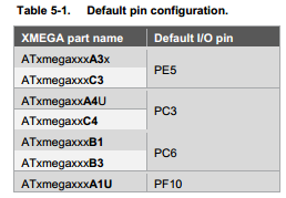
So, for my target it is Port C, pin 3. Consulting the xmega manual…

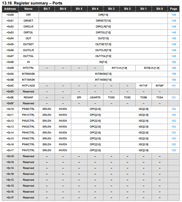
So, setting the direction for port C will address 0x0640 (offset is 0) and PIN3CTRL will be at 0x0653 (offset is 0x13).
To cut a long story short, the important lines in the disassembly are:
    800a:    f0 92 40 06     sts    0x0640, r15
...
    8010:    00 93 53 06     sts    0x0653, r16
...
    801c:    00 91 48 06     lds    r16, 0x0648
    8020:    03 ff           sbrs    r16, 3
...
    80de:    f0 92 53 06     sts    0x0653, r15
As an exercise, work out which registers are being accessed. The STS and LDS commands are direct store and load instructions. SBRS is “skip if bit in register is set”. In this case we can see bit 3 is being used, which is as it should be, and the value in register 16 is the IN value for the port.
Suppose we want to change the sensing pin to be Port D pin4 (physically pin 24 on a 44 pin xmega). This indicates a base address of 0x0660 and changing the instructions to:
STS  0x0660, R15
...
STS  0x0674, R16
...
LDS  R16, 0x0668
SBRS R16, 4
...
STS  0x0674, R15
Open Tiny Hexer and import the Intel Hex file appropriate to your chip from the AVR1916 zip file. Now it is just a case of changing the hex representation of the appropriate bytes. Note that the byte order of 0x0640 is reversed in the disassembly and in the HEX file. Here are some screenshots of Tiny Hexer after changing the required bytes:
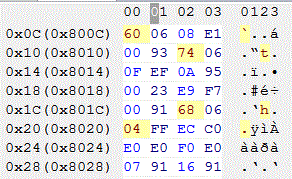
…
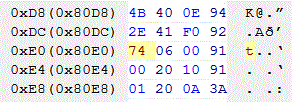
Now export from Tiny Hexer as Intel HEX, saving with a new name (!).
At this point, it is a good idea to run avr-objdump again, on the new HEX file, to make sure that it still makes sense to an AVR. I also did a file-diff on the new vs original disassembled files. The results are as follows, although there is also a block of FF that got inserted between code blocks. This has no effect, and simply reflects the fact that Tiny Hexer exported a continuous block rather than two blocks with a space in between.
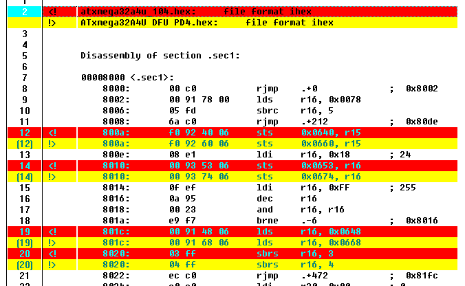 …
…

Looks like I got it right! Only the instructions I wanted to change got changed, and the flash memory addresses came out correct for a bootloader.
All that remains is to program this onto the chip with your programmer of choice (I use the Olimex AVR-ISP-MK2 clone since my Dragon utterly fails to even get the device ID 95% of the time), making sure the BOOTRST flag is correctly set if it is a new chip. Erase the chip, program and go!
A Cheat
If you can find two HEX DFU bootloader files for the same target chip, but with different sensing pins, a quick thing to do is to disassemble both and do a diff. I bet they will be from the same basic source code, and will quickly reveal which instructions need changing. Confession: that is how I got started on this problem.
Uploading Using DFU
To be honest, I think FLIP is a bit rubbish, and using the command line batchisp.exe is a pain in the arse. I’ve found dfu-programmer to be much nicer to play with (although the 0.7.1 version does contain a bug that fails to account for the xmega bootloader living in separate flash and so reduces the available flash for applications; this is fixed in 0.7.2 but is not released AFAIK at the time of writing).
I use dfu-programmer from Atmel Studio as an “external tool” via a small “bat file” command script.
In Atmel studio, point the external tool command at the .bat file and add the following into the “arguments” slot:
"$(ProjectDir)Debug\$(ItemFileName).hex" atxmega32a4u
To work, you do need to select the project file with the same name as the hex file before invoking the tool.
My .bat file just contains:
@echo off
REM supply the hex file location as 1st argument e.g. "dfu-programmer script argument blink.hex",
REM supply the target device as the 2nd arg e.g. atxmega32a4u

ECHO Erase, flash %1 and application launch.
ECHO Device = %2
ECHO ==========================================================
ECHO.

SET PATH=%PATH%;C:\Users\Adam\Desktop\dfu-programmer
dfu-programmer %2 erase --force
dfu-programmer %2 flash %1 --debug 2
dfu-programmer %2 launch --no-reset
ECHO -----------------------------------------------------------
Further Adventure?
I have not done this, but see this line:
800e: 08 e1 ldi r16, 0x18 ; 24
That is setting the value of register 16, which is immediately stored to PIN3CTRL in the original code. A quick look at the datasheet shows that, as expected, this is setting a pull-up on Port C pin 3. Fancy changing that?
… Or maybe change the SBRS to SBRC ?
Hi
Thanks very much for this! Due to tight PCB layouts I need to move the pin to the (practically redundant) port B of an xmega256a3U. Using Studio 6, damned if I want to learn another compiler suite for a trivial job.
Do it in the morning, this seems easy!
(Wondering, tho’, as the 256A3U has 8k for bootloader, whether or not Studio/GCC would be enough.
-Andy,Oulu, Finland.
Thank you for this idea! I was beating my head against this problem for a day and your solution is far easier & Quicker than the alternative of porting the bootloader to GCC. And thanks for the step by step instructions, I could have worked it out too, but you saved me a lot of pain.